Engineering & manufacturing in Exeter, New Hampshire, USA since 1961 [email protected]
Toll Free (888) 597-9255 Tel +1 603-778-2300 Contact
0%

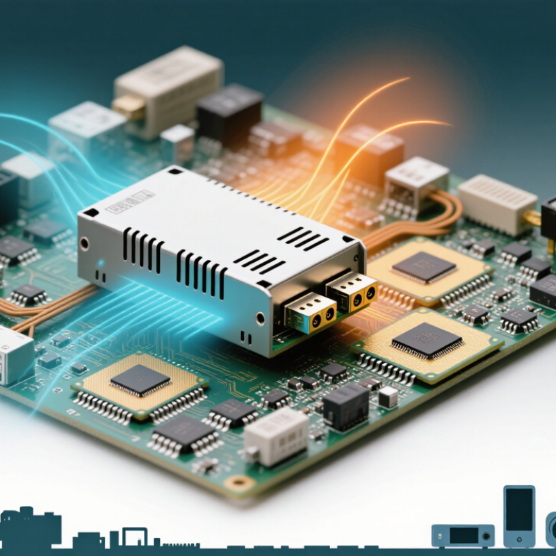
What are PCB Mount Power Supplies, and why do engineers continue choosing them for compact electronic systems? These modules convert incoming electrical energy into stable DC power. They mount directly onto a printed circuit board, reducing wiring, connector count, and assembly space. A typical unit may sit beside a processor, sensor, relay, or communication module. That short electrical path can improve layout control. It can also create new thermal and electromagnetic challenges.

Industry reports show sustained demand for smaller, more efficient power-conversion equipment. Grand View Research identifies miniaturization, energy efficiency, and embedded electronics as important market drivers. Mordor Intelligence also links power-supply growth with industrial automation, telecommunications, and consumer devices. However, report boundaries differ. Some include adapters and chargers, while others focus on board-level converters. The numbers are useful, but they are not perfectly comparable.

EMC authority Henry W. Ott offered a practical warning: “The best way to solve an EMC problem is to avoid it in the first place.” His advice applies directly to PCB Mount Power Supplies. Engineers must consider switching noise, heat spreading, creepage, clearance, and load transients before production. A compact board does not automatically mean a reliable design. Sometimes, a larger module performs better. That detail is easy to overlook. This guide examines construction, operating principles, ratings, thermal behavior, safety considerations, and real application choices. It also questions common assumptions, because efficiency figures alone cannot describe field performance.

What Are PCB Mount Power Supplies?

What Are PCB Mount Power Supplies?

What Are PCB Mount Power Supplies?

PCB mount power supplies are compact modules installed directly onto a printed circuit board. They convert incoming electrical energy into the voltage required by processors, sensors, relays, or communication circuits. Some accept alternating current and provide isolated direct current. Others regulate one DC voltage into another. Their small size saves panel space, but it also concentrates heat near sensitive components.

In practical designs, engineers check more than the rated output. They examine load changes, startup current, efficiency, insulation, and standby consumption. A 12-volt module may deliver its rating in open air, yet perform differently inside a sealed enclosure. Airflow matters. So does spacing.

Component placement requires care. Keep heat-producing parts away from electrolytic capacitors and temperature-sensitive sensors. Follow the recommended creepage and clearance distances. Copper traces must handle the expected current without excessive heating. Mechanical stress also deserves attention, especially where heavy cables connect to the board. A secure enclosure can prevent solder joints from carrying unnecessary force.

A common mistake is choosing a supply by voltage alone. That approach is incomplete. Noise, ripple, transient response, and protection features can affect the entire circuit. Designers sometimes trust a typical datasheet value too much. Actual results depend on layout, temperature, input quality, and load behavior. Testing under realistic conditions remains essential, even when the circuit appears stable on the bench.

How PCB Mount Power Supplies Work

A PCB mount power supply is a compact converter soldered directly onto a circuit board. It receives AC or DC input and delivers a controlled voltage to processors, sensors, relays, or motors.

Its operation begins with input protection, followed by rectification or switching. A transformer or inductor then adjusts voltage through high-frequency switching. Feedback continuously measures the output and corrects variations.

The control loop is the critical part. If the load changes suddenly, the controller changes the switching duty cycle within milliseconds. Capacitors and inductors reduce ripple before power reaches sensitive components. Isolation may also separate hazardous input energy from the low-voltage output.

Thermal design remains essential. Heat travels through copper traces, the package, and surrounding air. A small enclosure can quietly become a serious reliability problem. That assumption is incomplete.

Tips: Check the datasheet’s derating curve, not only its rated wattage.

MarketsandMarkets reported in 2024 that the global power supply market could grow at about 7% annually through 2029, driven partly by automation and connected electronics. These figures vary between research firms, so they should guide planning, not replace testing. In practical designs, engineers should measure ripple, startup behavior, electromagnetic interference, and temperature under the worst expected load. IPC guidance supports careful spacing and thermal evaluation, but real boards still need validation. A supply may pass bench testing and fail inside a sealed enclosure. That is worth remembering.

Key Components and Design Features

What Are PCB Mount Power Supplies?

Key Components and Design Features

PCB mount power supplies convert incoming voltage into stable power for circuits. Their compact design allows direct installation on a printed circuit board. In practical testing, the transformer or switching stage usually draws early attention. However, protection parts matter just as much. Fuses, surge limiters, and isolation barriers help control dangerous faults. Rectifiers and capacitors smooth the input. Regulator circuits then maintain a steady output under changing loads.

Thermal design often decides whether a supply performs reliably. Heat sinks, copper areas, and airflow paths should match the expected load. A crowded board may trap heat around switching components. This can shorten service life. Electromagnetic interference also needs control. Short current loops, suitable filtering, and careful grounding reduce unwanted noise. Designers should check creepage and clearance distances, especially when mains voltage is present. A clean schematic does not guarantee a safe physical layout.

Tips: Measure ripple at the actual load, not only during no-load testing. Leave space around hot components. Verify insulation requirements against current safety standards. In one early prototype, the output looked stable, but the connector became unexpectedly warm. The cause was a narrow copper path, not the power circuit itself. That result was easy to miss and worth reconsidering. Load testing, temperature checks, and fault simulations reveal weaknesses before production. Use an enclosure and mounting method that support cooling without stressing the PCB.

What Are PCB Mount Power Supplies? - Key Components and Design Features

Design Dimension Typical Data or Range Key Components Involved Design Significance
Power Conversion Type AC-DC or DC-DC; isolated or non-isolated Rectifier, switching transistor, transformer, inductor, controller IC Defines input compatibility, safety isolation, efficiency, and circuit topology.
Input Voltage Common AC input: 85–264 V AC; common DC input ranges: 5–36 V DC or 18–75 V DC Input fuse, EMI filter, bridge rectifier, transient suppressor A wide input range allows operation across changing supply conditions and utility systems.
Output Voltage Typical regulated outputs: 3.3 V, 5 V, 12 V, 15 V, or 24 V DC Feedback divider, reference circuit, PWM controller, output filter The output must match the load voltage and remain within the equipment’s tolerance limits.
Output Power Common PCB-mounted ratings: approximately 1 W to 100 W; higher ratings require careful thermal design Power switch, transformer or inductor, rectifier, heat-spreading copper Power rating determines component stress, board area, airflow requirements, and temperature rise.
Isolation Voltage Often 1.5–4 kV AC for isolated designs, depending on construction and safety requirements Safety transformer, optocoupler, isolation slots, reinforced PCB spacing Isolation separates hazardous input circuits from accessible or low-voltage output circuits.
Efficiency Typically 75–95%, depending on power level, topology, load, and input conditions Low-loss MOSFET, synchronous rectifier, optimized transformer or inductor Higher efficiency reduces wasted energy, enclosure heating, and cooling requirements.
Switching Frequency Commonly about 50 kHz to 1 MHz, depending on topology and power level PWM or resonant controller, switching transistor, gate driver Higher frequency can reduce magnetic component size but may increase switching losses and EMI.
Output Regulation Often within approximately ±1% to ±5%, depending on the design and load Voltage reference, feedback network, compensation components Stable regulation protects sensitive electronics from input and load variations.
Ripple and Noise Commonly specified from tens to hundreds of millivolts peak-to-peak, depending on bandwidth and load Electrolytic and ceramic capacitors, output inductor, LC filter Low ripple is important for analog circuits, sensors, communications, and precision measurement.
Protection Functions Overcurrent, short-circuit, overvoltage, overtemperature, and input surge protection Current-sense resistor, thermal sensor, clamp circuit, shutdown controller Protection features limit damage during abnormal operating conditions and load faults.
Thermal Operating Range Common commercial ranges begin near 0 °C and extend to 70 °C; industrial designs may cover approximately −40 °C to 85 °C Thermal sensor, heat-spreading copper, heatsink, derating control Temperature affects component lifetime, available power, reliability, and safety margins.
PCB Mounting Method Through-hole pins, surface-mount terminals, or a combination of both Terminal pins, mounting holes, solder joints, mechanical supports The mounting method influences assembly process, mechanical strength, serviceability, and board layout.
Creepage and Clearance Distance is application-specific and depends on working voltage, pollution level, insulation class, and applicable safety standard PCB slots, spacing between traces, insulating barriers, transformer construction Adequate spacing reduces arcing and surface leakage risks in isolated power sections.
EMI and EMC Design Designed to control conducted and radiated emissions within applicable limits Common-mode choke, differential inductor, X and Y capacitors, shielding Filtering and careful PCB routing reduce interference with nearby circuits and communication systems.
Typical Applications Embedded controls, industrial instrumentation, sensors, communications equipment, and consumer electronics Power module, control circuitry, connectors, filtering, and protection components PCB mounting saves space and simplifies integration when the power supply is installed directly on the main circuit board.

Common Types of PCB Mount Power Supplies

PCB mount power supplies convert electrical energy directly on a circuit board. Their small footprint helps designers save cabinet space and shorten wiring paths.

Common types serve different input and output needs. AC-DC modules accept mains voltage and provide low-voltage DC for control boards. They usually include isolation, filtering, and safety barriers. DC-DC converters work from an existing DC source, such as a battery or a 24-volt control rail. Step-down versions reduce voltage, while step-up versions increase it. Buck-boost designs can do both when the input changes widely.

Isolation matters.

Isolated DC-DC supplies separate input and output circuits through a transformer. This design can reduce shock risks and limit unwanted ground-current paths. Non-isolated converters are often smaller and more efficient, but they share a common electrical reference. Designers also choose between open-frame and encapsulated supplies. Open-frame units release heat more easily, while encapsulated units resist dust, moisture, and vibration. Regulated models maintain a steadier output during load changes. Unregulated models cost less but may require additional control circuitry.

In practical board reviews, thermal performance often exposes the real difference between types. A module may meet its rated current at room temperature, yet require derating inside a sealed enclosure. I once underestimated heat near a connector, which raised ripple and caused unstable operation. The datasheet was correct; my layout assumptions were not. Check clearance, creepage, switching noise, and capacitor temperature before selecting a PCB mount power supply.

Applications and Selection Considerations

What Are PCB Mount Power Supplies?

Applications and Selection Considerations

PCB mount power supplies convert incoming electrical power into a controlled output for circuit boards. They are soldered directly onto the board, saving cable space and simplifying assembly. Typical applications include industrial controllers, measurement instruments, communication equipment, building sensors, and compact medical electronics.

Selection begins with the electrical requirements. Confirm the input voltage range, output voltage, rated current, and peak load demand. A 12-volt rail may need extra current during motor startup or wireless transmission. Check isolation requirements when the input and output connect to different safety domains. Leakage current, insulation rating, and creepage distance also deserve careful review.

Thermal behavior often determines real reliability. A supply rated for 20 watts may deliver less inside a sealed enclosure. Measure twice. Review the derating curve, ambient temperature, airflow, and copper area around the mounting pins. Excess heat can shorten capacitor life and create unstable output voltage. Electromagnetic interference is another practical concern. Test conducted and radiated emissions with the actual load, enclosure, and cable layout, not only on a development bench.

Mechanical details can cause unexpected delays. Verify pin spacing, board thickness, mounting orientation, and access for inspection. Protection features such as short-circuit, overcurrent, and overtemperature control improve fault tolerance. Certification requirements vary by market and application, so documentation should be checked before layout approval. A smaller module may appear efficient, but it can complicate cooling and rework. That trade-off is easy to underestimate.

FAQS

What are PCB mount power supplies?

They are compact power modules soldered directly onto printed circuit boards. They convert incoming AC or DC into controlled output voltage.

Where are PCB mount power supplies commonly used?

They support industrial controllers, sensors, measuring instruments, communication equipment, and compact medical electronics. They also power processors, relays, and small motors.

How do these power supplies regulate voltage?

They use switching circuits, transformers, inductors, capacitors, and feedback control. The controller adjusts switching duty cycles when the load changes.

What electrical specifications should engineers check?

Check input range, output voltage, rated current, peak load, ripple, efficiency, and startup behavior. Voltage alone is not enough.

Why is thermal design important?

Heat can build inside a sealed enclosure and shorten capacitor life. A module rated for 20 watts may deliver less without airflow.

How should components be placed around the power supply?

Keep hot parts away from capacitors and temperature-sensitive sensors. Provide suitable copper area, spacing, and safe creepage distances.

What protection features are useful?

Short-circuit, overcurrent, and overtemperature protection can improve fault tolerance. These features cannot replace proper testing.

What mechanical details require attention?

Verify pin spacing, board thickness, mounting direction, and cable strain. Heavy cables should not pull directly on solder joints.

How should designers validate a selected power supply?

Test it with the real load, enclosure, cables, and expected temperature. Measure ripple, electromagnetic interference, startup current, and output stability.

Conclusion

PCB Mount Power Supplies are compact power conversion devices designed to be installed directly onto printed circuit boards. They receive electrical energy from an input source, regulate or convert it through switching and control circuits, and deliver a stable output to other board-level components. Their small footprint, integrated construction, and efficient operation make them useful when space, reliability, and simplified assembly are important.

Key design features may include transformers, inductors, rectifiers, filters, feedback circuits, protection functions, and thermal management elements. Common types include AC-DC modules, DC-DC converters, isolated supplies, and non-isolated supplies, each suited to different voltage, current, and safety requirements. When selecting PCB Mount Power Supplies, engineers should evaluate input and output ranges, power rating, efficiency, isolation, operating temperature, electromagnetic compatibility, physical dimensions, mounting method, and expected load behavior. Proper selection helps ensure dependable performance and supports the long-term stability of equipment used in industrial controls, communications, instrumentation, consumer electronics, and embedded systems.

Seraphina

Seraphina

Seraphina is a dedicated marketing professional with a strong understanding of product strategy, customer needs, and market trends. As a key contributor to the company’s communications team, she regularly updates the corporate website with insightful, practical blog articles that help readers......