Choosing DIN Rail Power Supplies is not a simple matter of matching voltage and wattage. In real control cabinets, heat, space, wiring length, and load behavior can change performance significantly. A supply that works well on a test bench may struggle inside a crowded enclosure. This guide explains how to evaluate reliable options for industrial automation, building controls, security systems, and other low-voltage applications.
Begin with the electrical basics. Confirm the input range, output voltage, rated current, and required power margin. Motors, relays, valves, and communication devices may draw short startup surges. Allowing extra capacity can prevent nuisance shutdowns. However, oversized equipment is not always better. It may waste cabinet space and increase purchase costs. Check the manufacturer’s datasheet carefully, including derating curves, operating temperature, efficiency, ripple, and protection features. Small details matter.
Installation experience also deserves attention. Measure the available DIN rail space before ordering. Inspect terminal access, airflow, and cable routing around the unit. In a hot cabinet, a compact supply may need more ventilation than expected. Use recognized technical requirements and the manufacturer’s instructions when assessing safety and compatibility. Independent certifications can support confidence, but certification alone does not guarantee suitability for every installation. I have seen projects focus heavily on price and overlook maintenance access. That decision often creates avoidable delays later. A practical selection balances performance, reliability, serviceability, and future expansion. The right DIN Rail Power Supplies should support stable operation today without making tomorrow’s troubleshooting harder.
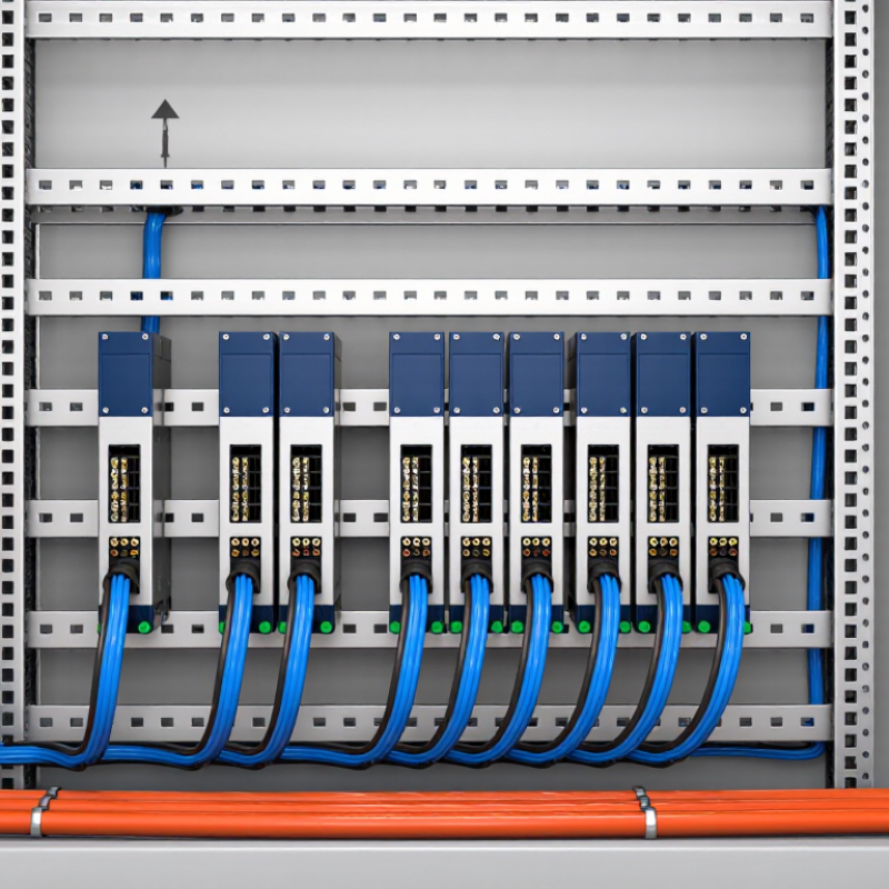
Selecting a DIN rail power supply starts with three numbers: load voltage, current, and power.
Confirm the equipment’s rated voltage, then check its allowable tolerance. Control devices may require 24 VDC, while sensors and relays can create short transients. Measure normal current and startup current separately. Do not size from the average alone. Startup matters. Use P = V × I to estimate demand, then add headroom for heat, aging, and expansion.
The IEA’s Electricity 2024 report estimates global data-centre electricity use near 460 TWh in 2022. It may exceed 1,000 TWh by 2026. This trend reinforces efficient conversion and careful thermal planning, even inside smaller control cabinets. Uptime Institute’s 2023 Global Data Center Survey also identifies power problems as a major outage concern. That evidence supports conservative sizing, though one calculation cannot predict every field condition. I have seen cabinets pass bench tests, then fail after warm installation. The missing factor was derating.
Tips: Record current during cold start, steady operation, and peak switching. Choose 20–30% reserve, but verify the datasheet’s derating curve. At 50°C, a nominal 10 A unit may deliver less. Check inrush compatibility, DC backup needs, fuse coordination, and terminal spacing.
Parallel units can improve availability, but they complicate fault diagnosis. That trade-off is easy to underestimate.
Sources: IEA, Electricity 2024; Uptime Institute, Global Data Center Survey 2023.
Selecting a DIN rail power supply starts with the control voltage, not the cabinet size. Under IEC 60204-1, 24 VDC is often a practical choice for machine controls, sensors, relays, and operator interfaces. It offers broad component compatibility and manageable current levels.
Choose 12 VDC when connected devices are designed for that voltage. Short wiring runs and compact instruments may benefit from it. However, current rises quickly as power increases, causing more voltage drop and heat. Check the full load, startup surge, and cable length. Small errors matter.
A 48 VDC supply can reduce current on longer control runs. That may simplify voltage-drop calculations and reduce conductor losses. Yet every sensor, valve, and interface must accept 48 VDC. Do not assume compatibility. IEC 60204-1 compliance also depends on protection, disconnecting methods, bonding, and the machine’s electrical design. The supply voltage alone is not proof of conformity.
In commissioning work, I measure voltage at the farthest load, not only at the power supply terminals. A clean 24 VDC reading in the panel can hide a weak field connection. Leave capacity for inrush and future additions, but avoid excessive oversizing without checking fault behavior. A simple rule can mislead. Recheck the actual devices, ambient temperature, and installation documentation before selecting 12, 24, or 48 VDC.
Choosing a DIN rail power supply requires more than selecting the highest wattage. Efficiency above 90% reduces cabinet heat, but the percentage depends on load. The U.S. Department of Energy’s 2023 technical support document shows that power supplies often perform differently at full, half, and light loads. Load matters. A unit rated at 92% may fall below 88% during standby operation. Check the efficiency curve, not only the headline number.
Ripple and regulation affect sensors, relays, and communication modules. The IEC 61204 series provides measurement guidance for low-voltage power supplies, while manufacturer test data should show conditions clearly. Compare ripple in millivolts, output regulation in percent, and test load ranges. A 30 mV ripple figure means little if measured only at 25°C and full load. Measure it yourself. Use short oscilloscope ground connections and test near the receiving device. Wiring can add surprising noise.
The European Commission’s Ecodesign studies commonly evaluate efficiency across several load points, rather than relying on peak performance. Apply that discipline to DIN rail selection. A supply with 91% efficiency, 20 mV ripple, and ±1% regulation may outperform a 94% unit with unstable light-load behavior. Thermal derating also deserves attention. In a crowded cabinet, every lost watt becomes heat. My own review would not treat “above 90%” as proof of quality; it is only a starting point. Datasheets sometimes omit transient recovery time, and that omission deserves questions.
Selecting a DIN rail power supply starts with the real load, not the label on the equipment. Add every sensor, relay, controller, and communication device. Then calculate the highest expected demand, including startup current. A useful design target is 30% power headroom. For a 24 V system drawing 4 A, the load is 96 W. Select at least 125 W, while a 150 W unit may provide better operating margin.
Heat changes the calculation. DIN rail supplies often deliver their rated power only within a specified ambient temperature range. Read the thermal derating curve carefully. Do not assume a 120 W supply can provide 120 W inside a hot, enclosed cabinet. At elevated temperatures, its permitted output may fall sharply. Check the actual panel temperature, not only the room temperature. Dark enclosures, nearby drives, and limited ventilation can add considerable heat.
Leave space around the supply when the installation guide requires it. Confirm the rail orientation, airflow direction, and terminal temperature limits. During commissioning, measure output voltage and cabinet temperature under realistic load. A brief bench test can hide a serious thermal issue. One common mistake is sizing for normal current while ignoring future expansion. Another is trusting a generic derating rule. Recheck the manufacturer’s published curve for the exact model and installation conditions. Some projects still need more than 30% headroom. That is not wasteful when reliability matters.
Use the following planning table to estimate the required power rating, select a practical nominal capacity, and verify operation under the actual enclosure temperature, mounting orientation, ventilation, and load profile.
| Application Profile | Calculated Load | Minimum Rating with 30% Headroom | Practical Nominal Rating | Approximate 24 VDC Output Current | DIN Rail Space Planning | Thermal Derating Verification | Selection Decision |
|---|---|---|---|---|---|---|---|
| Example Sizing Calculations | |||||||
| Small sensor and control circuit | 2.4 W continuous | 2.4 W ÷ 0.70 = 3.43 W | 5 W or higher | 0.10 A at 24 VDC | Use the manufacturer’s stated module width; allow additional space for wiring and airflow. | Confirm the unit can deliver at least 3.43 W at the maximum enclosure temperature. | Suitable when the load is stable and expansion is not expected. |
| PLC, relay, and sensor group | 6.8 W continuous | 6.8 W ÷ 0.70 = 9.71 W | 12 W or higher | 0.50 A at 24 VDC | Check neighboring devices for heat transfer and maintain the specified side clearances. | Use the derated output curve rather than the 25 °C nameplate rating when the cabinet is warmer. | Good general-purpose choice if the thermal curve supports 9.71 W at site conditions. |
| Compact automation control panel | 14.5 W continuous | 14.5 W ÷ 0.70 = 20.71 W | 24 W or higher | 1.00 A at 24 VDC | Reserve room for terminal blocks, fuse protection, and cable bend radius. | Verify rated output at the highest internal air temperature, especially in a sealed enclosure. | Recommended when the supply has adequate thermal margin at full operating temperature. |
| Multiple valves, relays, and instrumentation | 28 W continuous | 28 W ÷ 0.70 = 40 W | 48 W or higher | 2.00 A at 24 VDC | Evaluate the total heat generated by the power supply and adjacent equipment. | Check whether the derating curve reduces available power below 40 W at the enclosure’s maximum temperature. | Use a larger rating if startup or simultaneous solenoid loads are significant. |
| Distributed I/O and actuator panel | 42 W continuous | 42 W ÷ 0.70 = 60 W | 72 W or higher | 3.00 A at 24 VDC | Consider wider equipment, additional ventilation, and separation from other heat-producing devices. | Confirm the unit maintains at least 60 W after temperature, mounting, and input-voltage derating. | Preferred for higher loads or systems with foreseeable future expansion. |
| Key Selection Dimensions and Verification Criteria | |||||||
| Output voltage | Match the connected equipment’s permitted DC input range. | For a nominal 24 VDC system, check the actual adjustment range and tolerance. | 24 VDC is common in industrial control systems. | Output current equals power divided by voltage. | Confirm the device is designed for the intended DIN rail profile and mounting direction. | Review voltage-related derating at low and high AC input conditions. | Select the correct voltage before comparing power ratings. |
| Continuous load power | Sum the normal operating power of all connected loads. | Include loads that can operate at the same time. | Do not use the nominal rating as the normal operating load. | I = P ÷ V | Higher current usually requires larger terminals and more conductor space. | Use the manufacturer’s output-current curve at the actual ambient temperature. | Base the calculation on measured or documented load data. |
| Power headroom | Reserve at least 30% above the calculated continuous load. | Required rating = Load ÷ 0.70 | Round up to the next practical standard rating. | Apply the same margin to current when voltage is fixed. | Allow space for future modules and wiring changes. | Power headroom does not replace thermal derating analysis. | A larger rating may be necessary when inrush, expansion, or high ambient temperature exists. |
| Ambient temperature | Use the highest expected air temperature inside the enclosure, not only the room temperature. | Account for heat from drives, relays, transformers, and adjacent power supplies. | Compare the required output with the rated output at that temperature. | Output current may decrease as temperature rises. | Follow the specified clearance around ventilation openings and heat-generating surfaces. | Never assume the 25 °C rating remains available at elevated temperatures. | Choose a higher-power or lower-loss design if the thermal curve is insufficient. |
| Mounting orientation | Install the supply in the orientation specified by its technical documentation. | Horizontal, upside-down, or side mounting can change heat dissipation. | Do not apply a vertical-mount rating to another orientation without verification. | Current capability can be reduced by restricted convection. | Maintain the required top, bottom, and side clearance. | Verify derating for the exact mounting position used in the final cabinet. | Use the approved orientation for predictable thermal performance. |
| Input voltage and frequency | Check the actual AC supply range and frequency at the installation site. | Consider brownouts, generator operation, and long cable runs. | Universal-input models may have different thermal behavior across the input range. | Input current and power factor may affect upstream protection. | Coordinate the device footprint with protective devices and disconnects. | Review any derating or output limitation at low input voltage. | Verify the full input range, not only the nominal mains voltage. |
| Startup and inrush demand | Identify loads such as motors, valves, capacitors, and long cable runs. | Continuous-load headroom alone may not cover short-duration peaks. | Check peak-current, overload, and startup behavior in the technical documentation. | Compare peak current with the supply’s overload capability and duration. | Consider separate supplies for sensitive electronics and high-inrush loads. | Thermal protection may activate more often if overload events repeat. | Increase capacity or stagger startup when peak demand is substantial. |
| Protection and system coordination | Review short-circuit, overload, overvoltage, and overtemperature protection. | Ensure the selected protection method does not interrupt essential loads unnecessarily. | Coordinate upstream circuit breakers and downstream fuses with the supply’s specifications. | Verify that terminal and conductor ratings support the maximum current. | Provide accessible isolation and safe service clearance. | Check the recovery behavior after thermal or overload shutdown. | Document the final protection and wiring arrangement before commissioning. |
Choosing a DIN rail power supply starts with the control cabinet, not the catalog page. Check IEC 61000 test results for electromagnetic compatibility. These results indicate how the supply handles noise and avoids disturbing nearby equipment. In a factory, a motor starter may create sharp electrical interference. A supply with suitable immunity can keep the controller stable. However, compliance claims need careful reading. Some tests apply only to specific installation conditions.
UL 508 is important for industrial control equipment used in North America. Confirm that the certification covers the complete power supply category and its intended application. Do not rely on a familiar approval symbol alone. I have seen engineers overlook wiring, protective devices, and spacing requirements during installation. The supply may be certified, yet the final cabinet arrangement may still need review. That detail matters.
Check the IP rating against the real cabinet environment. IP20 may suit a clean, enclosed panel, but dust or dripping water requires stronger protection. Also compare the rated ambient temperature with the cabinet’s hottest internal point. Heat reduces available output power. A compact enclosure can become surprisingly warm. Leave ventilation space around the unit, and examine derating curves rather than only the headline wattage. I still recheck these curves after installation, because measured temperatures sometimes differ from design estimates. Small oversights can create large reliability problems.
Aim for about 30% headroom above the highest expected load. For a 24 V system drawing 4 A, the load is 96 W. A supply rated near 125 W may work. A 150 W unit offers more margin.
Add sensors, relays, controllers, and communication devices. Include startup current, not only normal operating current. Future expansion also deserves attention. Small loads can accumulate quickly.
Heat can reduce the permitted output power. A 120 W supply may deliver less inside a hot cabinet. Check the cabinet’s hottest internal point. Room temperature is not enough.
Read the exact model’s published derating curve. Do not trust a generic temperature rule. Check nearby drives, enclosure color, ventilation, and mounting space. I still recheck this after installation.
Measure output voltage and cabinet temperature under realistic load. Include startup conditions when possible. A short bench test can hide a thermal problem. Real conditions matter more.
Electromagnetic compatibility testing shows resistance to electrical noise. A motor starter can create sharp interference. Suitable immunity helps keep controllers stable. Read the test conditions carefully.
Confirm that the industrial control certification covers the intended supply category. Also review wiring, protective devices, spacing, and installation conditions. A certified supply does not guarantee a compliant cabinet. That distinction is easy to miss.
Match the IP rating to the actual cabinet environment. IP20 may suit a clean, enclosed panel. Dust or dripping water may require stronger protection. Inspect the enclosure honestly.
Follow the required rail orientation and airflow direction. Keep the specified space around the supply. Check terminal temperature limits. A compact cabinet can become surprisingly warm.
No. High temperatures, expansion, and difficult ventilation may require more. Extra capacity is not wasteful when reliability matters. I sometimes size too tightly. That deserves a second review.
Choosing the right DIN Rail Power Supplies begins with a clear understanding of your system’s electrical demands. Define the required load voltage, operating current, and total power consumption, then select a suitable 12, 24, or 48 VDC output according to the control and safety needs of the installation, including relevant IEC 60204-1 considerations. A properly matched supply improves reliability and prevents unnecessary energy loss.
When comparing options, look for efficiency above 90%, low ripple, and stable voltage regulation. Plan for at least 30% power headroom to accommodate startup surges, future expansion, and changing loads. Confirm the unit’s thermal derating performance when mounted on a DIN rail, especially in enclosed cabinets or warm environments. Finally, verify compliance with applicable IEC 61000 and UL 508 requirements, along with the required IP rating and ambient temperature limits. These checks help ensure dependable operation, safer installation, and longer service life.