 Power Conversion Engineering
Talk to an engineer (888) 597-9255
Products Power Conversion Engineering Choosing High Temperature Power Supplies in 2026 starts with the conditions around the equipment, not just the temperature printed on a product page. A control cabinet beside a furnace, for example, may experience radiant heat, dust, vibration, and restricted airflow at the same time. These details can affect service life and stable output. The actual operating environment matters.
Check the specified ambient and operating temperatures, then review any derating curves in the manufacturer’s datasheet. A unit rated for a high temperature may still deliver less power as surrounding air warms. Confirm the required voltage, current, load behavior, isolation, and protection features for your application. A label alone is not proof. Look for clear test conditions, installation guidance, and documentation that matches the exact model.
Cooling deserves practical attention. Measure the temperature near the supply, not only across the room, and consider what happens when filters clog or fans slow down. Allow space for airflow, and verify whether the design relies on forced cooling. Small installation choices matter. Compare efficiency, expected maintenance, warranty terms, and available technical support, rather than choosing on purchase price alone. For critical equipment, review evidence with a qualified engineer and test the selected supply under representative loads and temperatures before deployment. Datasheets can leave questions unanswered; that is worth admitting. A careful selection process reduces avoidable risk, but real-world validation remains essential.
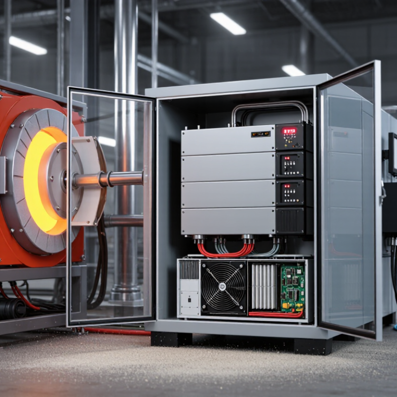
Define the real operating envelope before comparing power-supply ratings. Record the air temperature at the supply inlet, not only the room thermostat reading. Measure near the exhaust, inside the cabinet, and beside nearby heat sources. A 40°C room can hide a much hotter enclosure. Note peak temperature, daily duration, startup conditions, altitude, dust, vibration, and available airflow. Small details matter.
ASHRAE TC 9.9’s 2021 Thermal Guidelines list 5–45°C as the allowable inlet-temperature range for Class A4 data-center equipment. This is useful context, not a power-supply rating; verify the unit’s own specification. Set the required output voltage, continuous and peak current, ripple tolerance, and load profile. Include motor starts or brief current surges if they occur. Then check derating curves at the actual ambient temperature. A unit rated for a high temperature may still deliver less power there. Leave margin for blocked vents and aging fans. That margin is easy to underestimate. Record whether the supply sits in free air or a sealed cabinet, and test the hottest credible setup under full load. One assumption often slips through: average load is not peak load.
| Requirement | What to Define | Practical Selection Guidance | Verification Points |
|---|---|---|---|
| Maximum ambient temperature | Specify the highest air temperature at the power supply’s installation location, not just the room temperature. | Many industrial supplies are rated for operation up to approximately +70°C, but allowable output power may be reduced above a stated temperature. Higher limits are model-specific. | Check the manufacturer’s temperature-versus-load derating curve and the permitted mounting orientation. |
| Temperature inside the enclosure | Estimate air temperature near the supply after accounting for heat from nearby equipment, solar gain, and limited ventilation. | Use the local enclosure temperature as the design condition. Do not assume the supply sees the building’s ambient temperature. | Measure temperature near the unit during a full-load thermal test in the final enclosure. |
| Output power and derating | List continuous load, peak load, startup demand, and any planned future expansion. | Select a unit that can deliver the required load at the actual operating temperature and input voltage. Do not size it using its room-temperature headline rating alone. | Apply the documented temperature, input-voltage, and mounting derating factors; confirm overload behavior and peak-load duration. |
| Input supply conditions | Define nominal and worst-case AC or DC input voltage, frequency where applicable, and expected interruptions or dips. | Choose an input range that covers the real installation supply. Some units provide less output power at low input voltage. | Review input-range limits, low-line derating, inrush current, and any required upstream protection. |
| Output voltage and load behavior | Specify nominal voltage, adjustment range, current, acceptable tolerance, and load transient requirements. | Match the supply to the load’s steady-state and transient needs. Tolerance, ripple, and transient response limits should come from the equipment requirements. | Check specifications across line, load, and temperature conditions; confirm startup sequencing if multiple rails are used. |
| Cooling and heat dissipation | Define available airflow, clearances, enclosure ventilation, and whether fan noise or moving parts are acceptable. | Compare convection-cooled and fan-cooled options for the actual installation. Higher efficiency reduces heat, but does not remove the need to verify thermal performance. | At 500 W output and 90% efficiency, power loss is about 56 W: 500 × (1 / 0.90 − 1). Confirm that this heat can be removed. |
| Altitude and airflow restrictions | Record installation altitude and any restrictions caused by filters, sealed cabinets, or closely spaced components. | Reduced air density can impair cooling at elevation. Derating thresholds and required clearances vary by design. | Follow the product’s altitude and installation instructions; do not apply a generic altitude correction without checking its documentation. |
| Humidity, dust, and condensation | Define humidity range, condensation risk, dust or chemical exposure, and enclosure protection needs. | Many products specify humidity limits for non-condensing conditions. A high ambient-temperature rating does not automatically mean suitability for moisture or corrosive environments. | Check environmental ratings, coating options, enclosure requirements, and any restrictions on operation during condensation. |
| Protection and fault response | Identify required protection against overtemperature, overload, short circuit, and overvoltage. | Protection methods differ: a unit may limit current, shut down, or attempt automatic restart. The correct behavior depends on the connected load and system safety design. | Review recovery behavior and test representative faults without exceeding the product’s documented limits. |
| Safety and EMC compliance | Identify the end-product category, installation region, and applicable safety and electromagnetic compatibility requirements. | Relevant standards depend on the application; examples include IEC 62368-1 for audio/video and ICT equipment, IEC 61010-1 for measurement and control equipment, and IEC 62477-1 for power electronic converter systems. | Confirm certifications and conditions of use for the exact model and intended end application. Component approval alone may not certify the finished system. |
| Thermal validation and service life | Define expected operating hours, duty cycle, maintenance access, and acceptable failure or replacement intervals. | Component life and reliability depend on temperature, load, cooling, and design. A single rated operating temperature does not guarantee a specific service life. | Run the final assembly at worst-case ambient and load until temperatures stabilize; record hot spots and verify operation against documented limits. |
Record the lowest and highest AC or DC input, including brief dips, surges, and generator variation. Leave a reasonable margin.
Match voltage and continuous current to the load’s worst operating point. Include startup surges, motor demand, pulses, and capacitive loads.
Many supplies derate as ambient temperature rises. Check the output curve at the air temperature beside the unit.
No. Measure at the power supply’s air intake under full load. Not the room thermostat.
Check exposure to dust, oil mist, and washdown. Choose suitable protection, but remember that a tighter enclosure may restrict airflow.
Follow the specified orientation and clearance. Keep vents clear of cable bundles and nearby heat sources.
Run it at full load and measure temperatures. Recheck if equipment or cabinet airflow changes; I might miss a blocked vent.
No. They describe equipment inlet conditions, not a specific supply’s limits. Use the supply’s own derating curve and measured temperature.
Choosing High Temperature Power Supplies in 2026 starts with defining the operating environment, including ambient temperature, peak heat exposure, installation location, and expected duty cycle. Compare each unit’s rated temperature range with its derating curve, since available output may decrease as temperatures rise. Evaluate cooling options, such as convection or forced airflow, and ensure the supply’s input range, output voltage and current, and load capacity match the application’s requirements.
Also consider environmental protection, mounting constraints, airflow clearance, and the system’s overall thermal management. Check applicable safety and performance standards, review reliability information, and confirm that technical documentation clearly explains operating limits and maintenance needs. Finally, assess the supplier’s technical support and product availability to help ensure a dependable choice throughout the equipment’s service life.
